So If you haven’t seen it before, this is the arcade controller I have built for the game that has been controlling my life. If you can see, there are a whole lot of little blue arrows near the top that don’t look like they are good for sliding the hand across.

I have been working on a more accurate design so I thought, “Why not use arduino and a whole bunch of confusers all wired up in some convoluted way!” So I did..
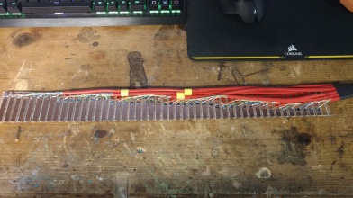
Shes no prom queen, but even the ugly girls… After a few hours of laser cutting, cleaning, sticking tiny pads of copper, stripping a metric crap ton of wire, and soldering it up all nice, the thing doesn’t work for squat. The wires may be too long, pads too close, or whatever but it does not sense through the acrylic and barely senses when touching the bare copper. My next plan is to re make this same board but with the wires as short as physically possible, no wires touching each other, and maybe if the stars align I will have it working enough for writing the code.

– I am very interested in the finished project. Give me a heads up when complete and I would love to buy a kit or pre-assembled controller.
LikeLike
Well the full controller is done, it is just the touch slider that is not looking promising. If you are interested, full controller are $500 but there are options for lowering the price by going with different options. I have a spreadsheet with those options if you would like.
LikeLike
Hey there!
I was wondering about the spreadsheet you mentioned here, since I’m planning to give a swing at building my own (via using all the information you provided on thingiverse). I also have a few specific questions I’d like to ask you whenever you have the time! Mainly small things such as changing the slider buttons to just 4 buttons (L1, R1, anything else, etc).
But feel free to reply here or privately anytime! Thanks again!
LikeLike
So the most up to date part list is the instructable page which has links to the parts which is here https://www.instructables.com/id/Project-Diva-FTCT-Arcade-Controller/
As for the sliders, 4 is the minimum with no problem, I just used 10 so I could slide my hand across. You can technically use just 2 if you wire each side to both triggers as double same note slides are very rare.
As for any other questions, ask away!
LikeLiked by 1 person
Ah, thank you for the quick reply and the link! Been ordering all the parts I need so hopefully it’ll get here in a timely matter ;P
I believe the only other question I have for now is regarding the two holes on each of the side walls. Apologies for the silly question, but since I didn’t see it mentioned anywhere, is that there so you have somewhere to grab onto when lifting the controller? Just curious is all lol.
LikeLike
Oh yes, and not entirely sure if you would happen to know about any alternatives to a paradise arcade fight breakout board? Unfortunately they’ve been out of stock for a very long time now (you can’t even request via ‘notify me’ on their site like their other products). Not sure how familiar you are with them, but I’ll be just searching around to see what else is out there, but if you happen to know anything off the top of your head would be greatly appreciated!
LikeLike
So Brook has a new board for the PS3/PS4 coming out this month which will work for this controller, it also supports audio for headphones. This is going to be the best option as the combination jack included fits in the hole on the back for the neutrik jack.
As for the side holes, they are to be plugged up or the start and option buttons can go there for different placements. On the new Brook board, there is also space for L3 and R3 buttons so those can fit in the side spots as well.
LikeLiked by 1 person
– Specifically, I’m looking for a working multitouch sensor. I already have the official Project Diva F Hori Arcade Controller but that’s a single touch sensor not located where the arcade cabinet sensor are.
LikeLike
Since it was not a easy job to make a touch pad for that, why not use an Android tablet or even Raspberry Pi with a touch screen/touchpad? If you can work with PCB, I guess make an Android/Linux app is not a big issue? Just throw all the determination to the app and everything will be ease, not to mention the art behind the pad or rainbow lights.I am awared that latency might be the biggest issue though.
LikeLike
Problem is there are no touch pads that have the dimensions I am looking for (approx 44×5 cm) and capacitive touch IC chips normally can’t sense a board that large so I am going to have to do something tricky to get something working.
LikeLike
I know it’s been awhile. Has there been any more progress on the touch slider? I’m looking into trying something like this as well, but I’m not even sure where to start yet. I’m going to start with a setup similar to yours, but maybe use two sticks mounted below to make due for now until a real slider can be made.
I’d love to hear about any progress…
Thanks!
LikeLike
Nothing as far as the big slider. There is one guy who kind of got one working but it’s very touchy. I actually just finished my first prototype of µDiva which has a real touch slider. I will have a brief post of that in the next half hour or so.
LikeLike
I’m working on the same thing. I have the basic touch sensors working with bare aluminium tape contacts and it works fine through paper and about 3mm of plastic. Now looking for a thicker piece of acrylic to test with but it seems like I could almost start working on the software side of things.
I’m thinking of getting a different touch controller chip anyway, because it turns out you can get some which will light up an LED for you when touched, instead of having to control that yourself. Actually sourcing said chip is another problem I guess.
LikeLike