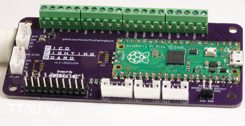
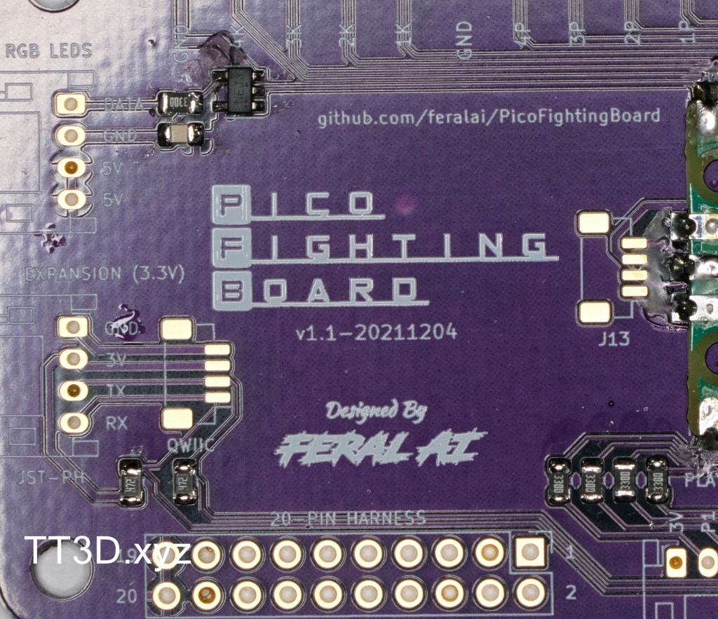
This soldering tutorial is for FeralAI’s Pico Fighting Board, an open source control board based on the Raspberry Pi RP2040 microcontroller. Documentation for the project can be found at https://github.com/FeralAI/GP2040
For more information on the Pico Fighting Board specifically, including the BOM for building this project https://github.com/FeralAI/PicoFightingBoard/
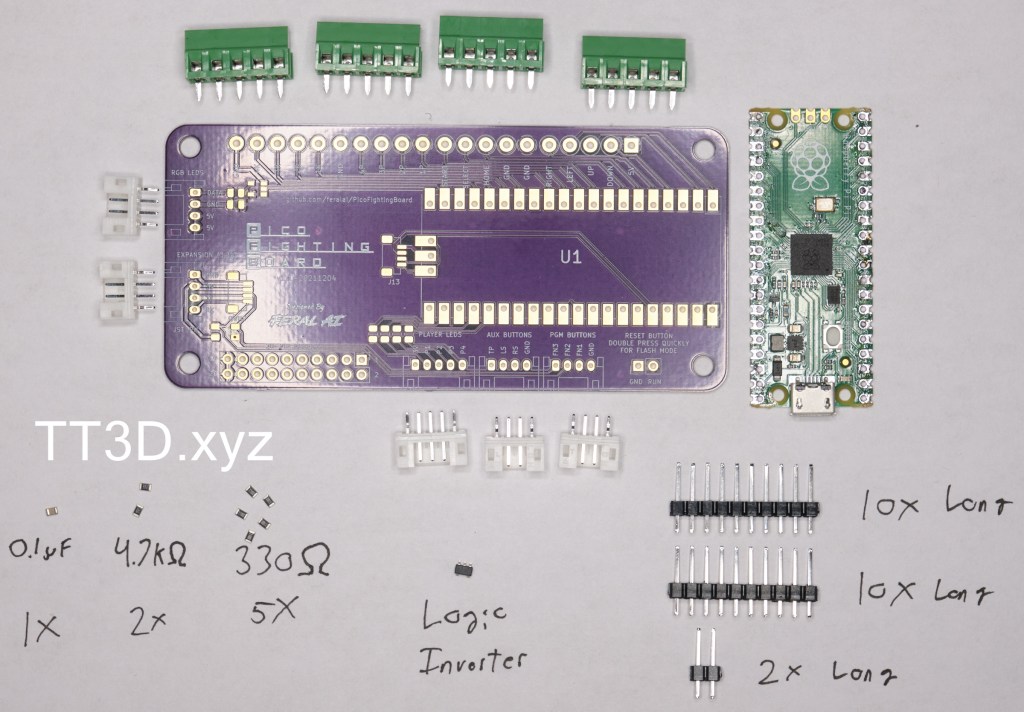
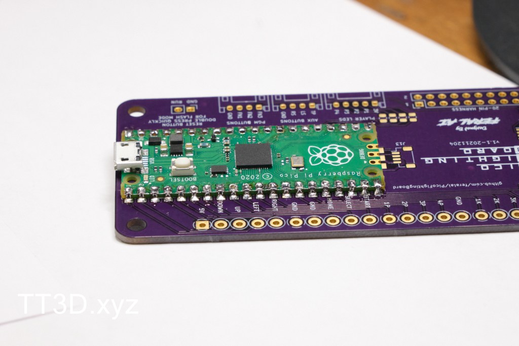
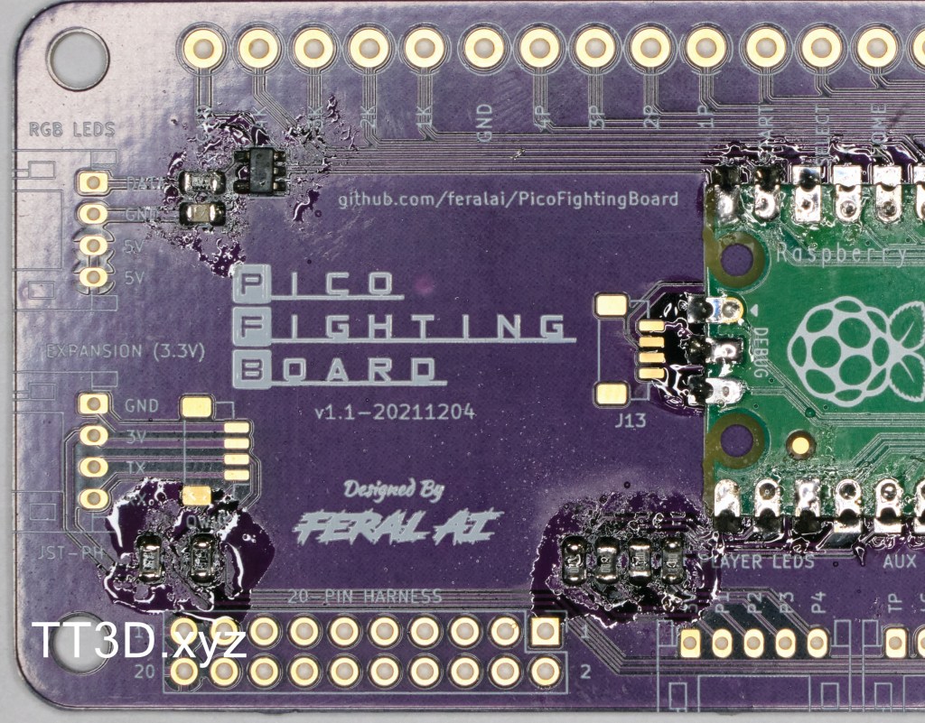
This is an overview of everything that will be required to solder this project. Not shown are the 2x StemmaQT connectors as I didn’t have any at the time, but I will add those steps later on when I get the parts.
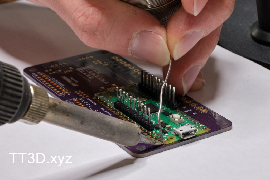
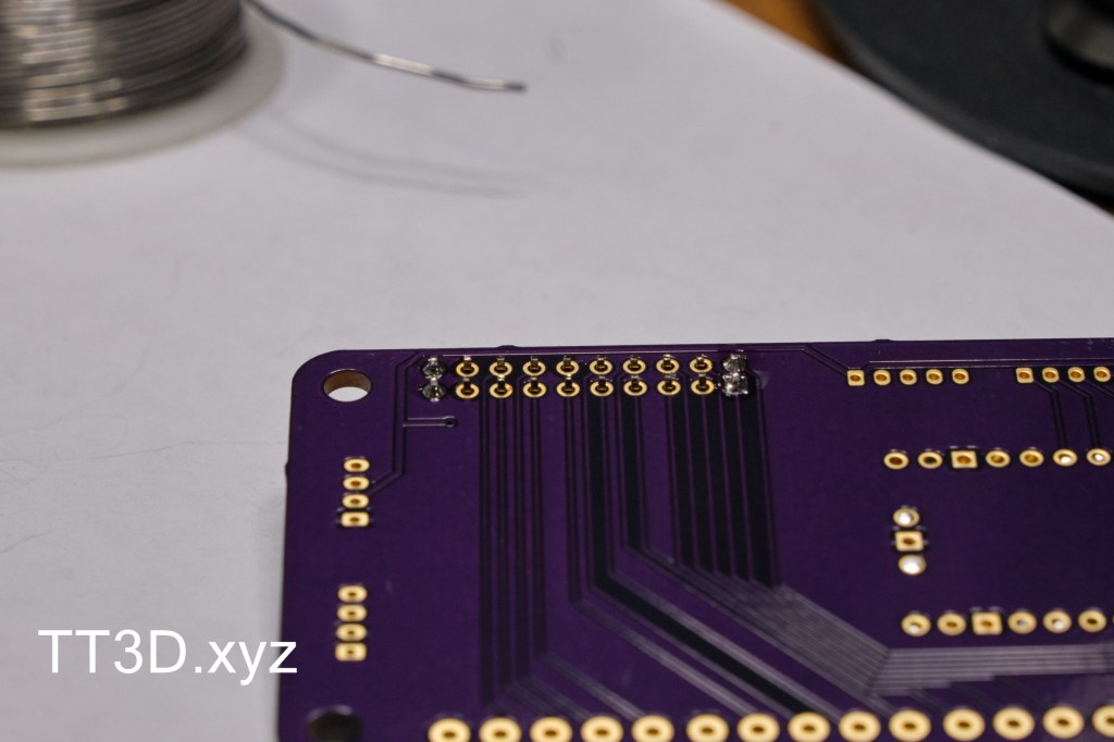
The first step of the build is to solder on the Pico board. Using the ten pin long header strips as alignment tools, place the Pico onto the PFB. My Pico has solder on it from a previous project, but this will not affect the board.
Starting with one corner, heat the metal contacts on both the PFB and the PICO. Having some solder on the iron tip will help to transfer the heat. Apply solder to the joint and then continue to heat for 1-2 seconds to allow the solder to flow.
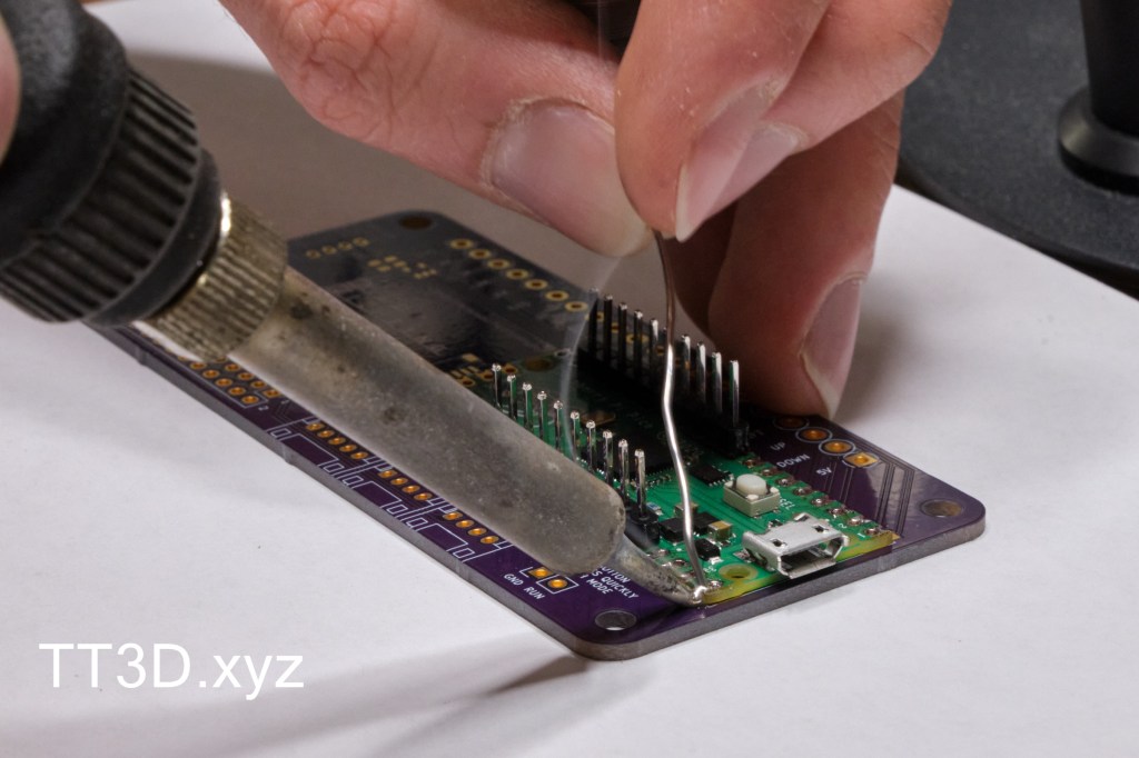
Do the same on the opposing corner.
And the remaining two corners so that the board is tacked down and aligned. It is now safe to remove the headers, failure to do so now may result in them getting soldered in place.
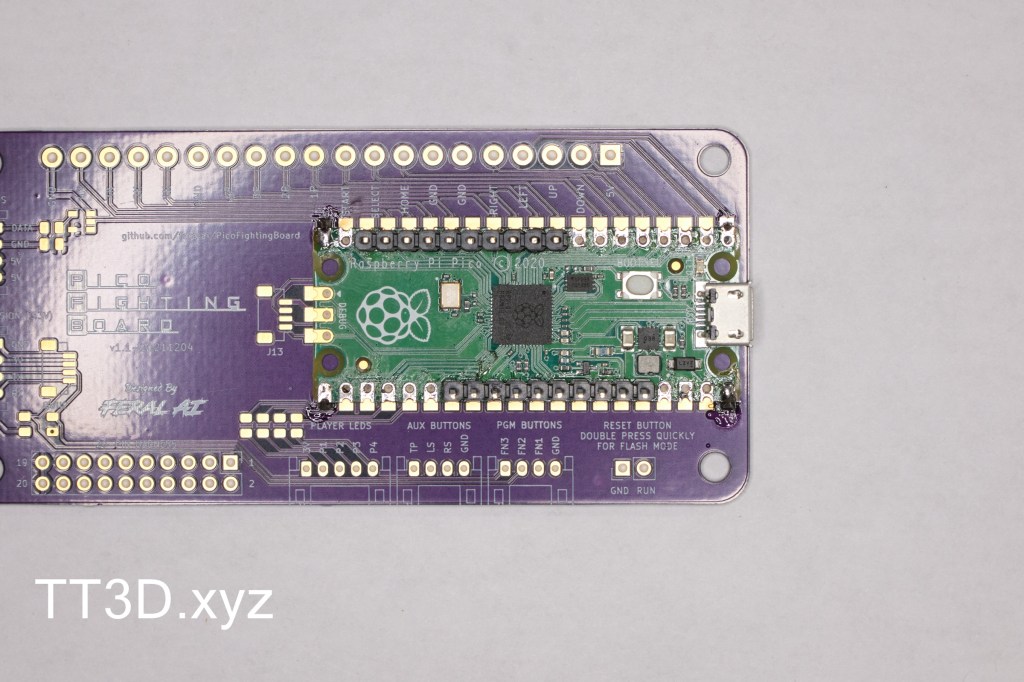
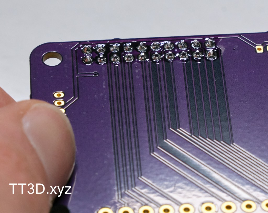
Solder the remaining pads, don’t forget to solder the three DEBUG pads as well.
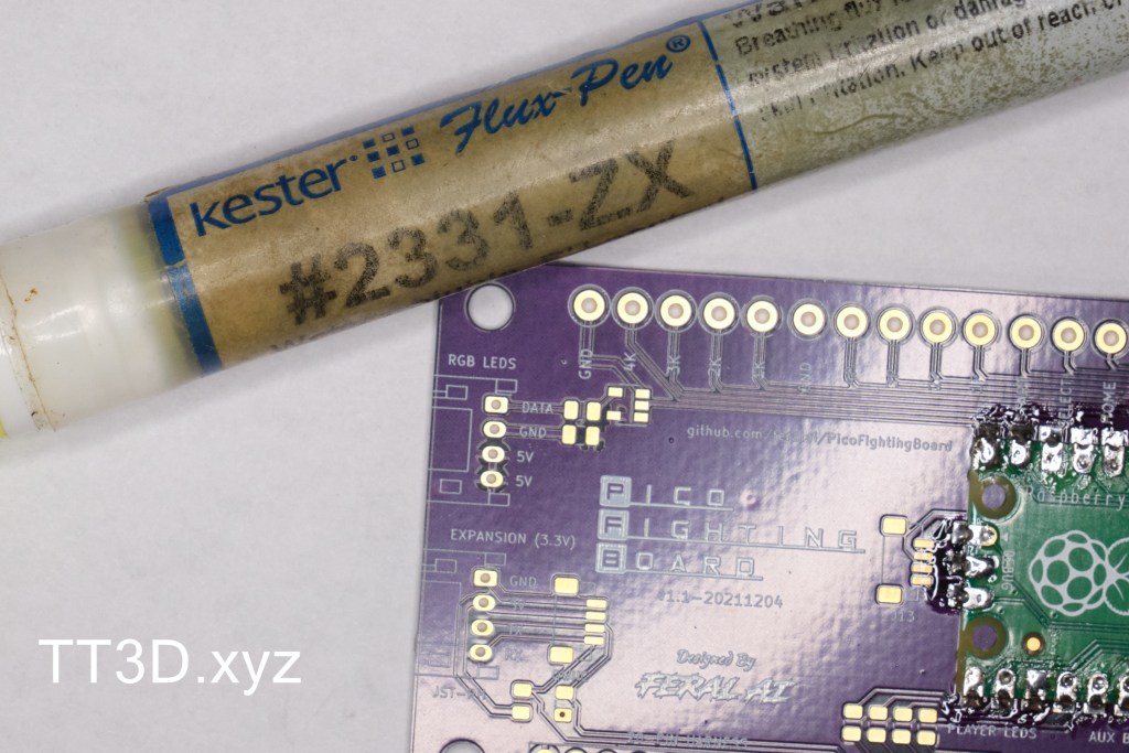
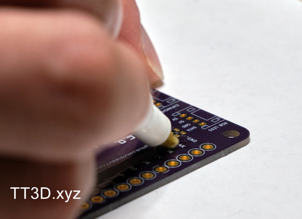
The next step is to solder on the logic converter. It is the small, 5 pin IC that will be placed on the 5 pads directly under the pin labeled 4k. If this is your first time soldering SMD components by hand, this is likely the hardest part of the board. Flux is a requirement when hand soldering SMD components, I use a Kester flux pen for this.
Place some solder on the one pad that is furthest from the others. This will be used for tacking down the component in a similar way to what was done with the Pico earlier.
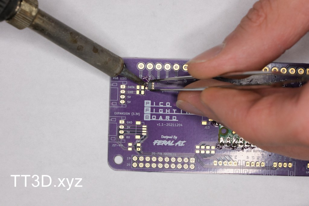
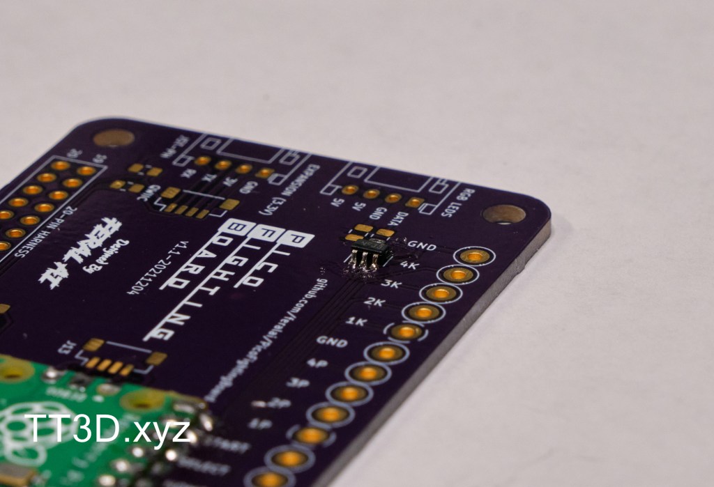
Use tweeters to hold the level shifter in place and heat the joint to tack it in place. If it needs to be adjusted at all, do that now by reheating and moving the component.
Tacked in place. The joint isn’t very strong as there was no flux used, you can see it also looks like a “cold joint”. This will be fixed next by using flux around the component and soldering the remaining pins.
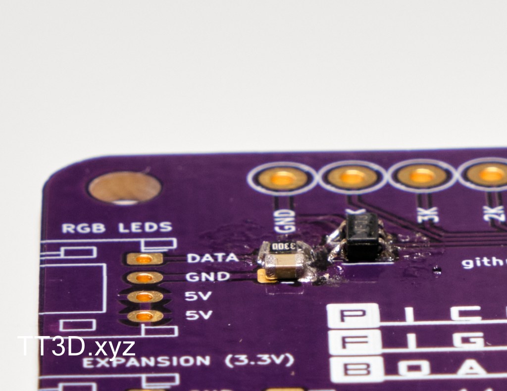
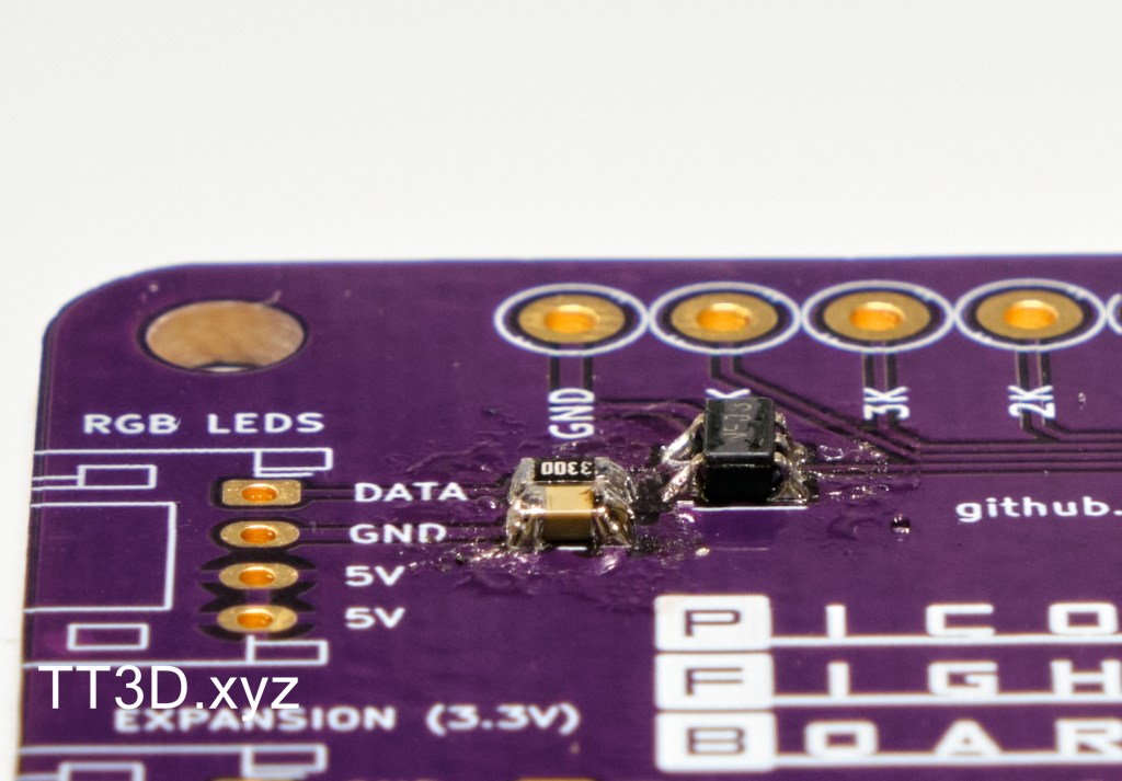
The next step is to solder one of the 330 ohm resistors. Resistors are not polarized so the orientation does not matter, it could even be upside down. The board is not labeled with the component references so be careful not to transpose the resistor with the capacitor. Just like the last component, one pad is used to tack the resistor in place, followed by flux and soldering the other pad.
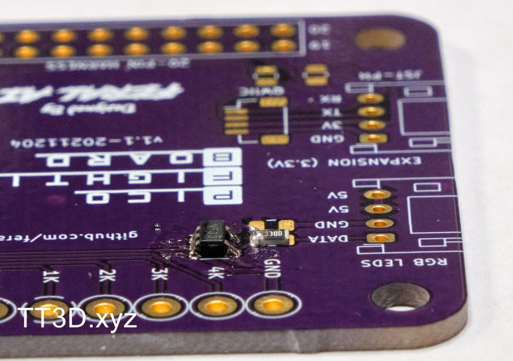
Next is the 0.1uF capacitor. This component is not polarized as it is a ceramic capacitor and not an electrolytic capacitor.
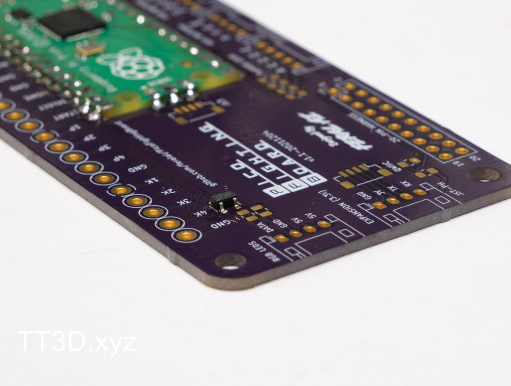
And done. Next is the remaining four 330 ohm resistors for the player LEDs. I tacked down all four at once here.
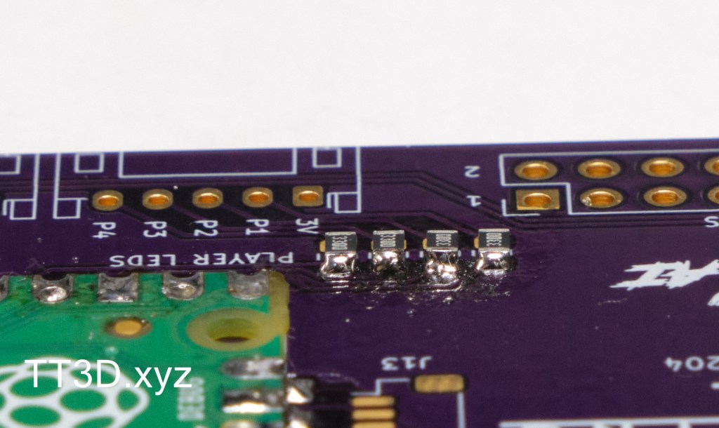
The last two SMD components are the 4.7k ohm resistors. Notice how they are labeled “472”. the “2” refers to two zeros to get 4700.
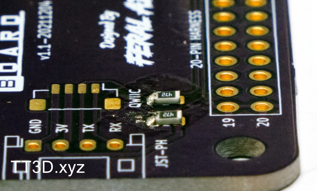
After soldering, there will be extra flux and residue. I used water washable flux so I give the board a cleanse with warm water, soap, and a toothbrush. Just make sure to dry it before plugging in.
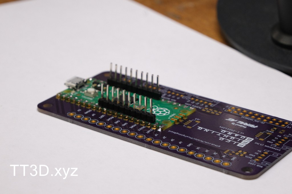
Next is the male header pins. If you are using 1x wide strips, be sure to tack them as shown so that you can adjust them if not parallel.
Perfect
Solder the remaining pins, as well as the two pin header for the reset button.
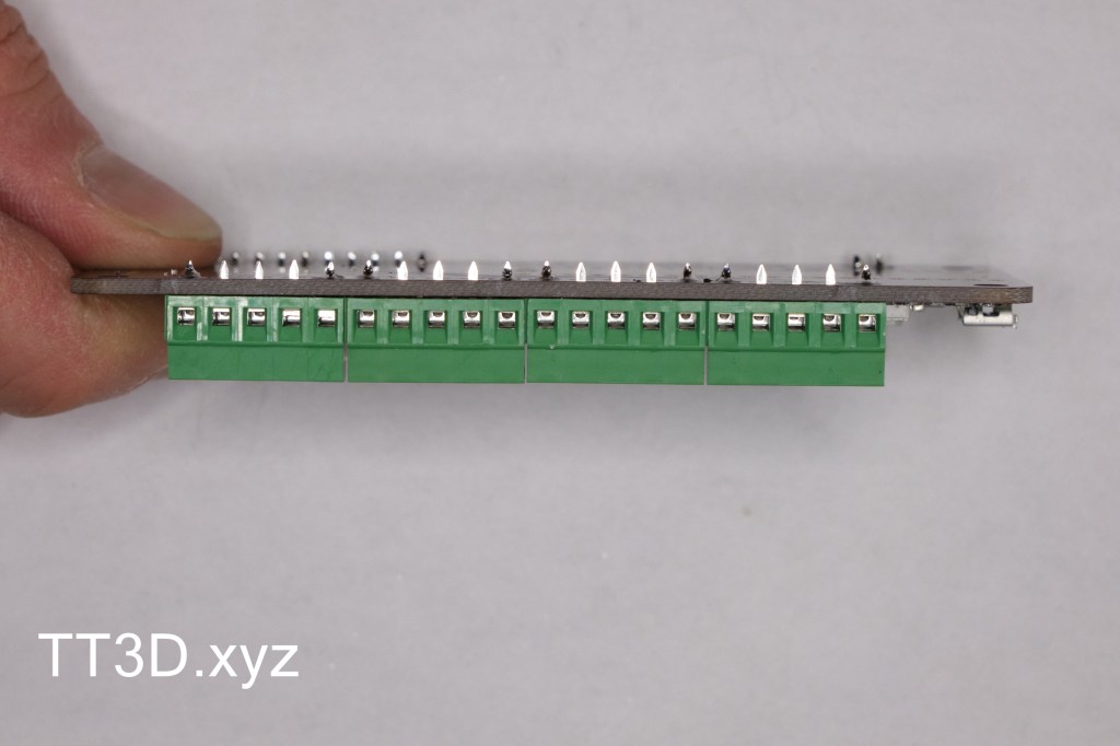
Next are the terminal blocks. With the header soldered, it is easy to place the board upside down resting on the blocks where everything will self align. To be safe, I don’t solder the blocks fully yet, using the same technique as before.
Check to make sure they are all flat, and solder the remaining pins.
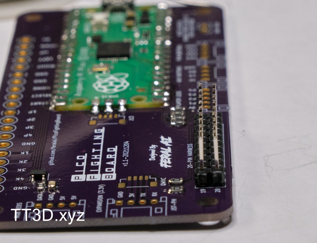
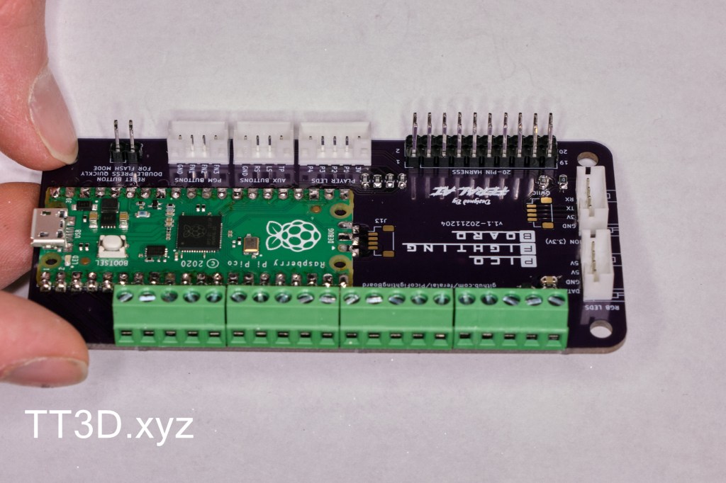
The last components are the JST style connectors. These will hold themselves into the board from friction making them very easy to solder. POLARITY MATTERS ON THESE! Make sure to reference the image, the opening on the connectors should face INWARDS on the board.
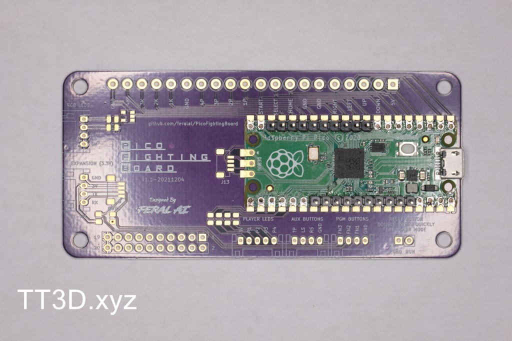
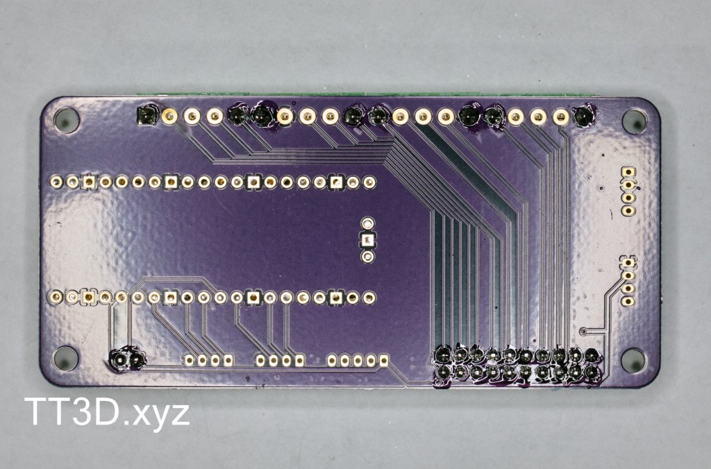
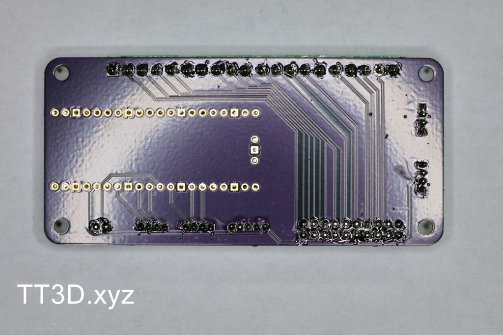
Make sure all connections on the back are soldered and you are ready to go. Note how the Pico outline pads are still gold on the back, this is fine as the joint is made on the other side of the board.
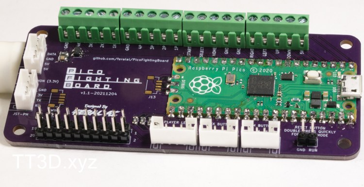
Complete! Make sure to load up the latest version of the GP2040 firmware and you are ready to go.